UnderstandingPCBManufacturing:FromDesigntoFinalProduct(understand 怎么读)
Design and Layout Preparation
Printed Circuit Board (PCB) creation begins with electronic design automation (EDA) software. Engineers convert circuit schematics into physical layouts, defining copper traces and component placements. Design rules check (DRC) ensures proper spacing between conductive paths and drill hole alignment. Gerber files become the universal blueprint, containing layer-specific data for copper, solder mask, and silkscreen. Advanced designs may incorporate impedance control for high-frequency signals and thermal management features.
Material Selection Criteria
Substrate materials determine PCB performance characteristics. FR-4 epoxy laminate remains standard for general applications due to its cost-effectiveness and flame resistance. High-frequency circuits require low-loss materials like Rogers RO4000 series. Flexible circuits employ polyimide films, while metal-core PCBs use aluminum substrates for thermal dissipation. Copper foil thickness ranges from 0.5oz to 2oz (17-70μm), selected based on current-carrying requirements and manufacturing capabilities.
Fabrication Process Overview
The subtractive method forms circuit patterns through copper etching. Clean rooms maintain controlled environments during lamination, where heat and pressure bond copper-clad layers. Photolithography transfers designs using UV-sensitive photoresist and precision exposure equipment. Chemical etching removes unwanted copper, leaving functional traces. Multilayer boards undergo sequential lamination with prepreg insulating layers. Controlled depth drilling creates through-holes and vias, followed by electroless copper deposition to establish interlayer connections.
Critical Imaging Techniques
Direct imaging systems project circuit patterns onto photoresist-coated panels without physical masks, enabling rapid prototyping. Laser direct imaging (LDI) achieves 25μm line width resolution for dense layouts. Liquid photoimageable solder mask (LPSM) application uses similar photolithography processes, creating protective coatings with precise openings for component soldering. Automated optical inspection (AOI) compares produced layers against original designs, identifying defects like open circuits or copper shorts.
Plating and Surface Finishing
Electroplating reinforces through-hole connections and surface conductors. Copper deposition builds up barrel thickness in plated through-holes (PTH), while nickel-gold finishes provide oxidation resistance. Common surface treatments include HASL (Hot Air Solder Leveling), ENIG (Electroless Nickel Immersion Gold), and OSP (Organic Solderability Preservative). Immersion silver serves as a cost-effective alternative for lead-free soldering. Each finish impacts solderability, shelf life, and compatibility with assembly processes.

Quality Control Measures
Electrical testing verifies circuit continuity and isolation. Flying probe testers check individual boards without custom fixtures, while bed-of-nails testers enable high-volume production validation. Cross-section analysis examines plating quality and layer alignment in multilayer boards. Thermal stress testing assesses solder joint reliability through multiple reflow cycles. IPC standards govern acceptance criteria, with Class 2 (industrial) and Class 3 (high-reliability) specifying different tolerance levels.
Assembly and Component Mounting
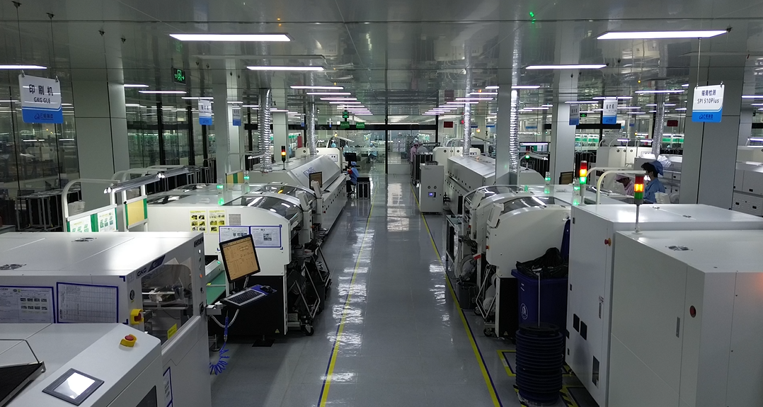
Surface mount technology (SMT) dominates modern PCB assembly. Solder paste application through stencils precedes high-speed component placement by pick-and-place machines. Reflow ovens create permanent solder joints through controlled heating profiles. Through-hole components require wave soldering or manual insertion. Mixed-technology boards combine SMT and THT processes. Conformal coating may be applied post-assembly for environmental protection in harsh operating conditions.
Final Product Validation
Functional testing replicates real-world operating conditions. In-circuit testing (ICT) verifies individual component performance using test points designed into the PCB. Boundary scan techniques test digital circuit functionality through JTAG interfaces. Environmental stress screening (ESS) exposes completed boards to thermal cycling and vibration. Burn-in testing operates boards at elevated temperatures to identify early-life failures. Final inspection checks labeling, mechanical dimensions, and cosmetic requirements.
Documentation and Traceability
Manufacturing documentation packages include assembly drawings, bill of materials (BOM), and test procedures. Unique serial numbers enable tracking through production stages. Material certifications ensure compliance with RoHS and REACH regulations. Revision control systems manage engineering change orders (ECOs) while maintaining historical records. Traceability data supports failure analysis and warranty claims, particularly in automotive and medical applications.
Environmental Considerations
Waste treatment systems neutralize acidic etchants and recover copper from spent solutions. Water recycling reduces consumption in rinsing processes. Lead-free soldering complies with global environmental directives. Dry film photoresist residues undergo proper chemical disposal. Many manufacturers pursue ISO 14001 certification to demonstrate environmental management commitments. Energy-efficient equipment and process optimization minimize carbon footprints throughout production.
Industry-Specific Adaptations
Medical PCBs demand ultra-high reliability and biocompatible materials. Automotive electronics require vibration-resistant designs and extended temperature range components. Aerospace applications utilize specialized conformal coatings and hermetic packaging. Consumer electronics prioritize miniaturization and cost-effective manufacturing. Industrial control systems emphasize long-term stability and surge protection. Each sector imposes unique material, testing, and certification requirements on PCB production.
Prototyping vs. Mass Production
Rapid prototyping services employ different tooling approaches compared to volume manufacturing. Laser-cut solder stencils replace etched stencils for short runs. Panelization strategies optimize material usage differently for prototype panels versus production panels. Quick-turn fabrication accepts looser tolerance limits to accelerate delivery. Mass production requires full validation of assembly fixtures and test jigs. Economies of scale impact material purchasing and process optimization decisions.
Technical Challenges and Solutions
High-density interconnect (HDI) boards require microvias and sequential lamination. Embedded component technology integrates passive elements within substrate layers. Thermal management issues in power electronics drive innovations in metal-core and insulated metal substrate designs. Signal integrity challenges in high-speed designs necessitate advanced simulation tools and controlled impedance manufacturing. Flexible-rigid combinations demand specialized handling equipment and stress relief design features.
